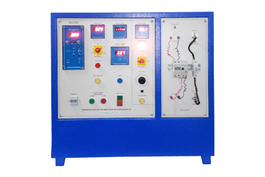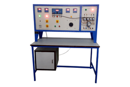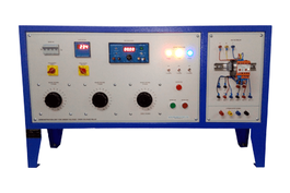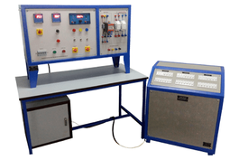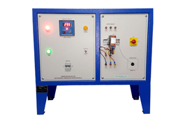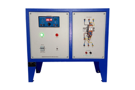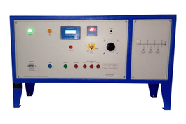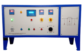


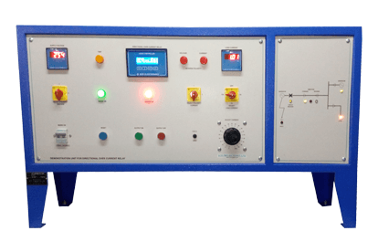
This is a demonstration panel to show the working of “DIRECTIONAL OVER CURRENT RELAY”. A protective relay is a device designed to trip a circuit breaker when a fault is detected.
A directional relay uses an additional polarizing source of voltage or current to determine the direction of a fault. The fault can be located upstream or downstream of the relay's location, allowing appropriate protective devices to be operated inside or outside of the zone of protection.
Measurement accuracy (voltage & current): 1%
Pre-settable polarities for demonstrating direction
Sequence of led’s to indicate direction of current flow.
Single Phase Variable Current Source 0-10V at 20 Amps.
Input supply : ac 230v 50/60 hz +/-10%
Simulated 2 feeder arrangement two for two limbs.
Arrangement to mount two number Directional Over Current Relay
2 MCBs (with slow response) one in each feeder.
Digital Ammeter 2 No. to indicate feeder current and one DAM to indicate ‘FAULT’ current.
Universal Digital Time Interval meter to measure Trip Time.
Arrangement to create fault in both the feeder with LED indications of flow Directions.
The test bench is generally offered as a standard issue, but can be designed as per the customer specs
The test bench simulates the direction with respect to the relay by dictating the polarities of the voltage and the current and demonstrates the working of the directional overcurrent relay
