


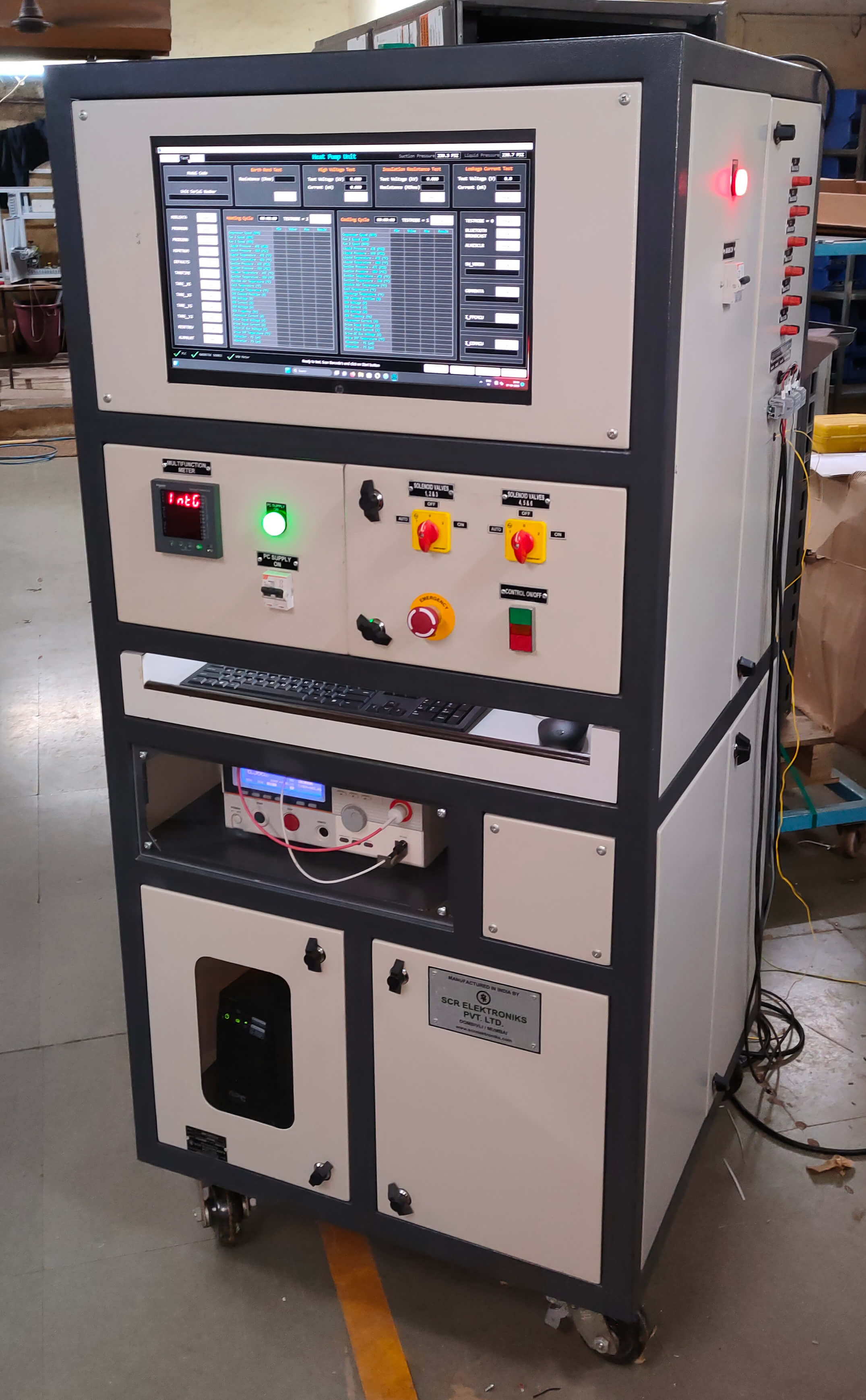
The Test Bench will have only PC modes of operation. All the tests will be carried out sequentially and the Data will be displayed and stored on PC. Lab VIEW based software and Siemens make PLC as an Interface module will be used to control the whole sequence. Option will be given for selection of test. If in different models of AC Tests are different, then that can be done by selecting the type no. (model) of AC
Earth Bond Test
In this test 10Amp AC current will be passed through Earth Path and the resistance of that Path will be measured and displayed on PC Screen. If the resistance is more than the set value (0.1 Ohms). Fail indication will be given & test will be terminated
Solid state source will be used for HV Test and Insulation Test
High Voltage Test with Ramp up / Down facility
In this test 0 to 6kV AC/DC Solid State source will be provided. High voltage (1.5kV) will be connected between live parts and will have metal body of the AC. If the leakage current will be more than the set value Fail Indication will be given & test will be terminated. Facility to set trip current from 1mA to 40mA for AC & 1mA to 10mA through PC
Insulation Test (Megger Test)
In this test 500V DC will be applied across the live parts in OFF condition and metal body of AC and the insulation resistance is measured and displayed on PC Screen. If the resistance is less than the set value 'Fail' indications will be given and test will be terminated
Earth Leakage Current Test
This test will be carried out with Run (Performance) Test. Rated Supply will be given to the AC and Leakage Current of Earth Path is measured and displayed on the PC Screen. If the current is more than the set value. Fail Indication will be given & Test will be terminated. Facility to set current limit 1mA to 15mA on PC. Leakage Current will be added for each device for comparing the limit
Performance (Run Test)
In this test rated voltage will be applied to the AC and current, wattage will be displayed on PC. Testing will be followed by 19/22C, 19/22d, 19/22e, 19/22f, 19/22j, 19/22j points
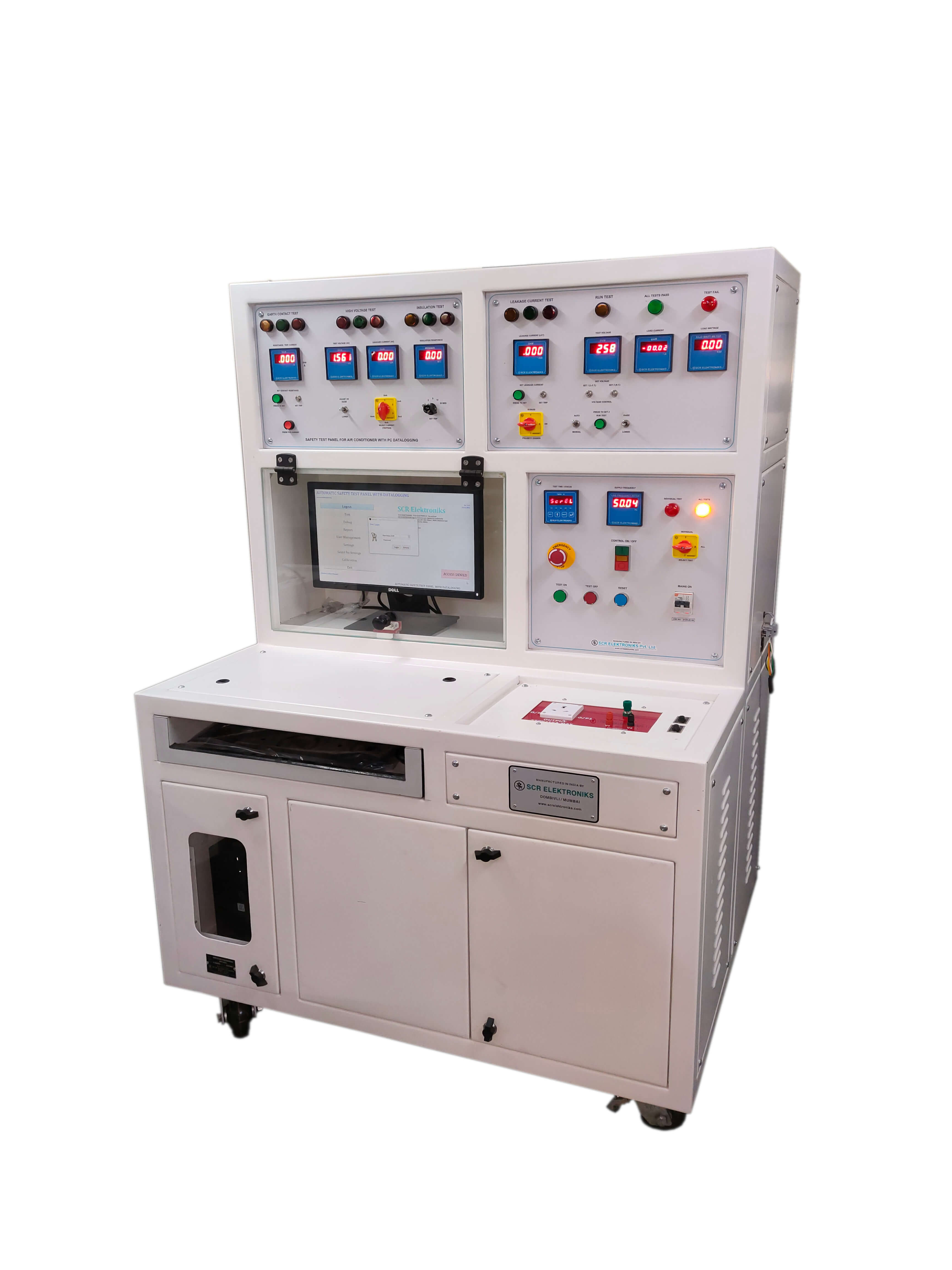
The testing set up for Air Conditioner is designed to carry out the tests as per the IS 302-1979. It broadly consists of testing facilities for following tests
Earth Contact Test
The set-up will consist of adjustable current source of 0-30 Amps. with open circuit voltage not exceeding 12 Volt. The set current can be observed on meter by pressing the push button provided. This Current will be allowed to pass in Earth Contact of Air Conditioner & the drop across the Earth path will be monitored and will be displayed on digital meter in terms of Ohms. In case it exceeds the set value (0.1 Ohms in our case) it will indicate the Failure. This setting can be done with the help of pot meter and can be viewed on digital meter by pressing "Press to Set" push button. The timer adjustable from 1 to 5 sec. will be provided to switch Off the Current after set time. The setting value can be re-adjusted to compensate the cable resistance value. The setting also can be seen on display
High Voltage Test
High Voltage Tester with Voltage adjustment from 0 to 1.5 KV with Tripping Current settings of 2,4,5,6,10 mA, selectable with switch, will be provided. Normally the Output Voltage will be adjusted at 1.5 KV. If the Current exceeds set value the output will be disconnected with "Fault" indication. Setting will be possible without making "HT” ON. Separate HT ON & Timer Start Button will be provided. Timer will be settable up-to 1 Min. The Digital Meter will indicate the leakage current. The tripping setting will be done through switch marked with 2, 4, 5, 6, 10 mA.
Insulation Test
Digital Megger (500V DC) with 20 Meg. Ohm. Range for indication. When the insulation resistance detected is less than 2 mega Ohm the "failure" indication will be provided
Leakage Current Test
The circuit is arranged as per the diagram shown in IS 302 - 1979 : clause 13.2 (figure no.5) with earth removed and equipment kept insulated. (The voltage will be present on the body of the equipment). When the 1.06 times rated Voltage (244 V) is applied to the Air Conditioner the Current flow through meter is monitored and displayed on the digital meter and if it exceeds 0.210mA., the "Fail" indication will be given. The test will be carried out by changing the connections automatically. The tripping value for both the cases will be 0.210mA. This value is also settable, with potmeter, between 0 to 1.000mA and displayed on meter by pressing "Press to Set" push button
Performance Test
The Set-up will compr ise of Variable Voltage Source to adjust supply Voltage 1 Phase 0-270 AC 16 Amp maximum
Note: Leakage current Test will be carried along with Performance Test
The above-mentioned Tests will be carried out automatically one by one and if the failure is observed the Test will be terminated and can be proceeded with Manual override. In manual mode individual test can be carried out
The total sequence of operation and annunciation carried of with the help of Micro Controller system
Input Supply – Single Phase 230V AC 50 Hz 25A max. with MCB protection for input supply
Note : The panel will be floor mounting type
Datalogging on PC :
PC Datalogging comprises of :
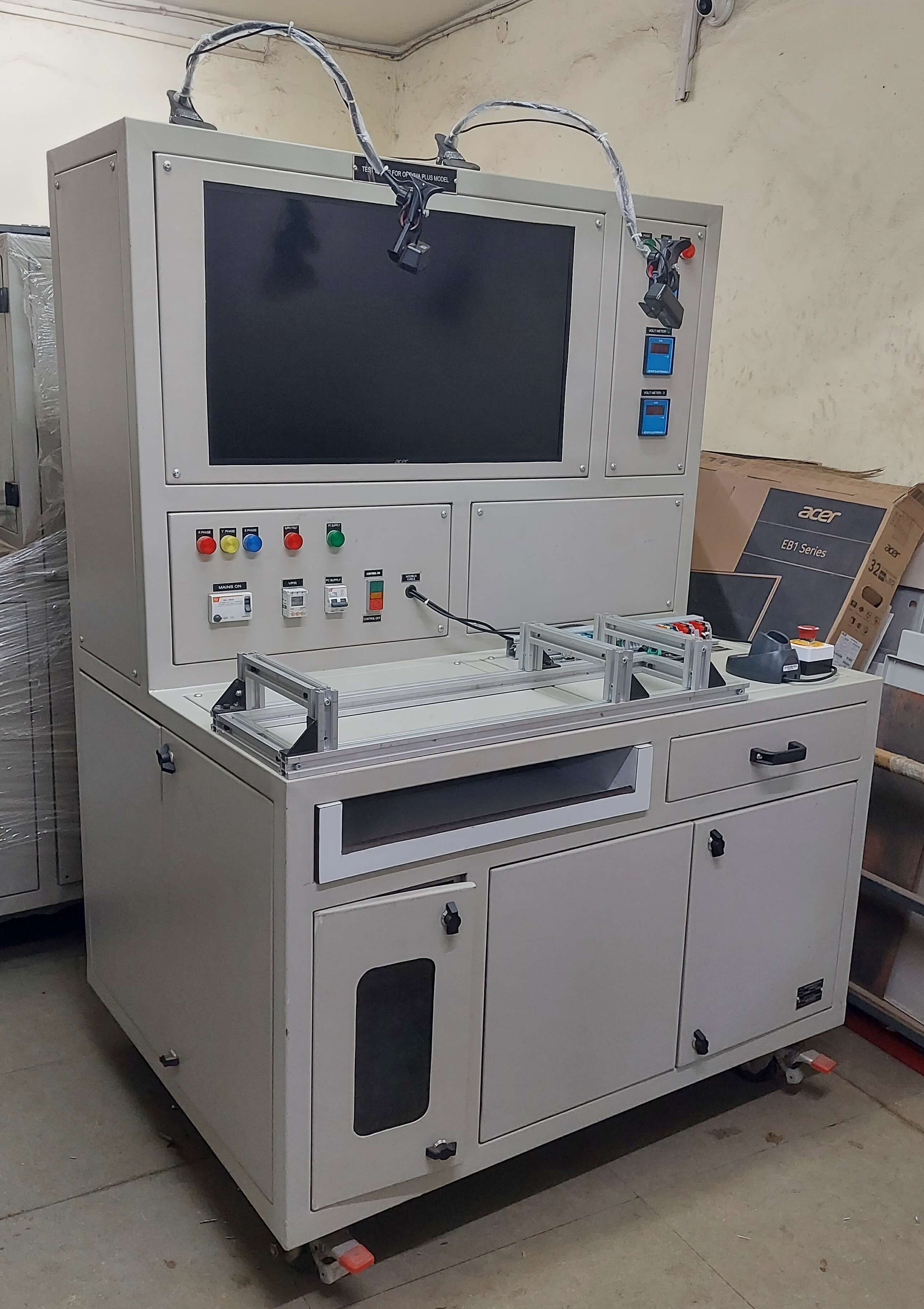
Comprises of
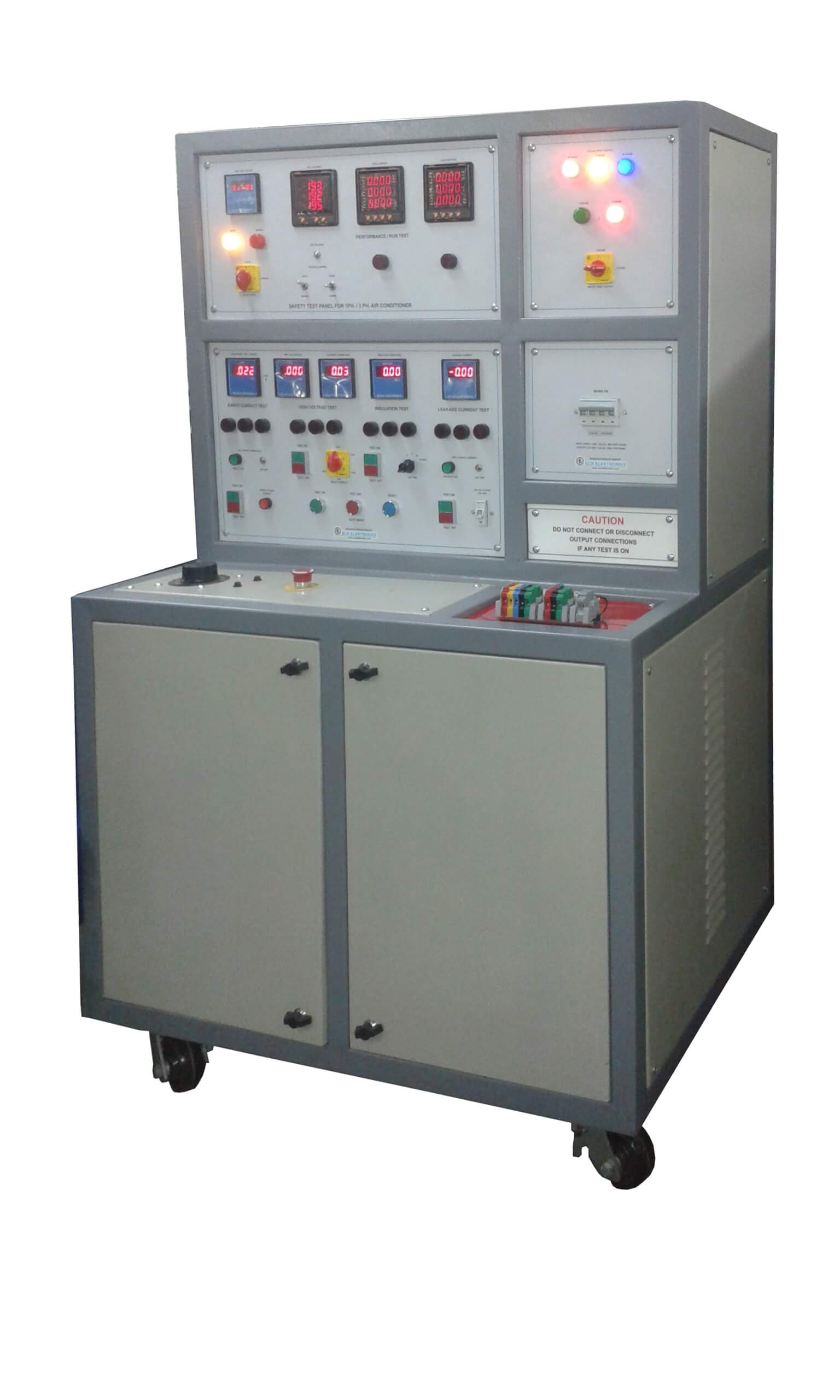
The testing set up for Air Conditioner designed to carry out the tests as per the IS 302-1979. It broadly consists of testing facilities for following tests
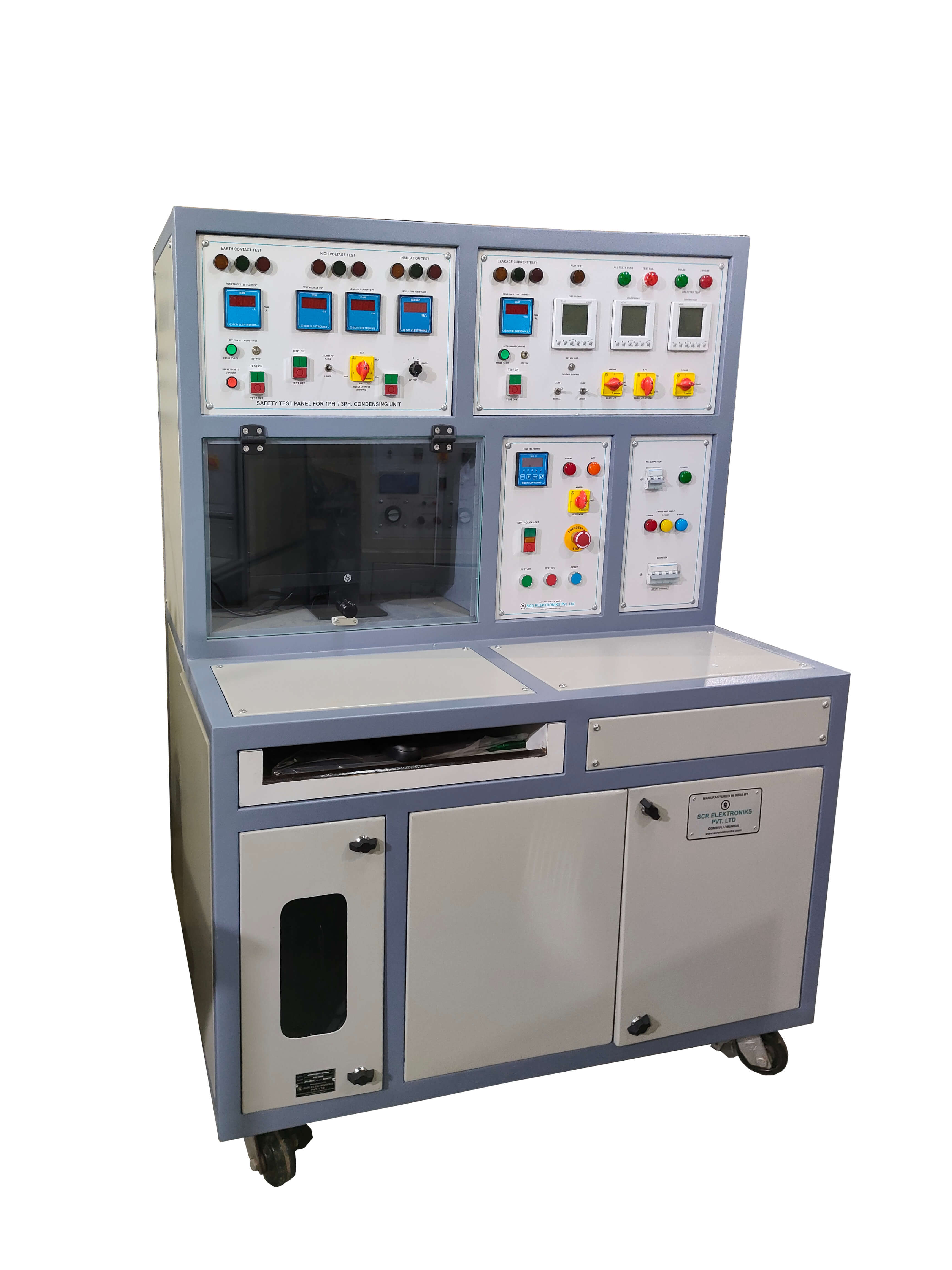
The testing set up for condensing unit designed to carry out the tests as per the IS 302-1979. It broadly consists of testing facilities for following tests
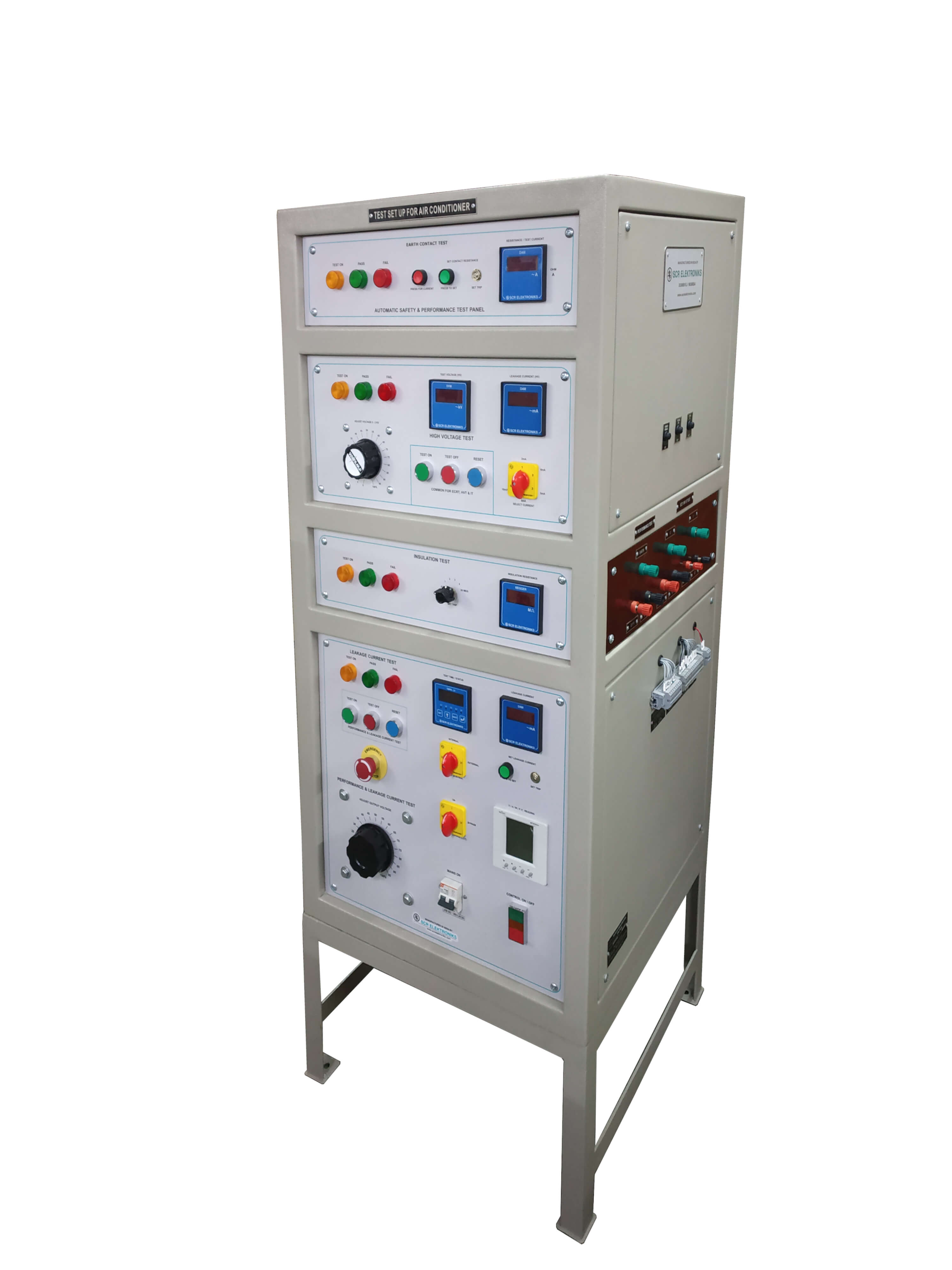
The testing set up for domestic electrical appliances is designed to carry out the tests as per the IS 302
It broadly consists of testing facilities for following tests :